
The Royal Danish Opera Roof

1. Royal Danish Opera from across the harbor
The Royal Danish Opera is among the most iconic buildings in Copenhagen. Sitting right on the harbor and across two of the most touristic spots in Denmark, Amalienborg (royal residence) and Frederik’s Church, it is hard to not spot the Opera when visiting Copenhagen.
This building is impressive in many ways, but it is undeniably cool to stand right in front with an almost floating roof above you. This article aims to explain in a simplified way some of the logic of how this roof works.

2. Front side of roof and building
The Copenhagen opera house was built in only four years, which is really quick for such a building, starting construction in 2001 and finishing in 2005. Designed by the architect Henning Larsen and engineered by Rambøll, among the many challenges, one of the biggest requirements was to make the roof as thin as possible while also allowing some natural light in.
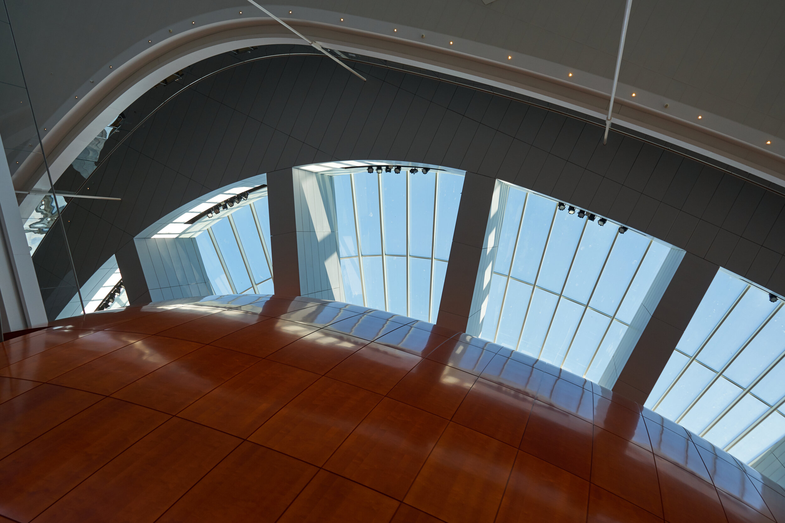
3. Roof windows seen from inside the Opera House
Uniqueness of the Roof
This roof is really fascinating because of three things: it is huge, thin, and hollow. It is 158 meters long, 90 meters wide and has a maximum depth of just 3 meters.
It is also interesting to point out that the back (east) and front (west) roof do not connect in the middle, so each side works independently. Both sides are quite similar, but the real challenge was the front roof that extends way past the walls of the building. The roof overhang is 21 meters on the sides, 31 meters at the front, and the maximum overhang is 41 meters measured from the last side column to the corner of the roof.
What is an overhang and how does it work?
A very important aspect to remember understanding structures is the difference between stiffness and strength, two different words we mistakenly use interchangeably.
Stiffness: how likely your element is to bounce back to its original shape after being loaded.
Strength: how much load you can apply without it breaking or bending permanently.

Imagine you hold a piece of paper at the edge of a table, something as simple as that is an overhang, also known as a cantilever. But it is not useful in any way. Even though this paper is strong enough to not break or bend permanently by supporting its own weight, it is not stiff enough, it bends too much to be useful. You could never place a pencil on this paper without it falling.

If you replace the paper sheet for cardboard, the thickness makes the cardboard stiffer than paper so its ability to resist force is higher. The thicker your cardboard, the less it sags and the more pencils it can support.
You can also strengthen and stiffen your overhang by making it shorter. Try moving your cardboard in and out of your table and see when it can support a pencil at the end. Let’s say you need to support more pencils and actually can’t change the length of your overhang; you go for other materials. If you grab a book, you can probably make a really long cantilever that easily can support many pencils.
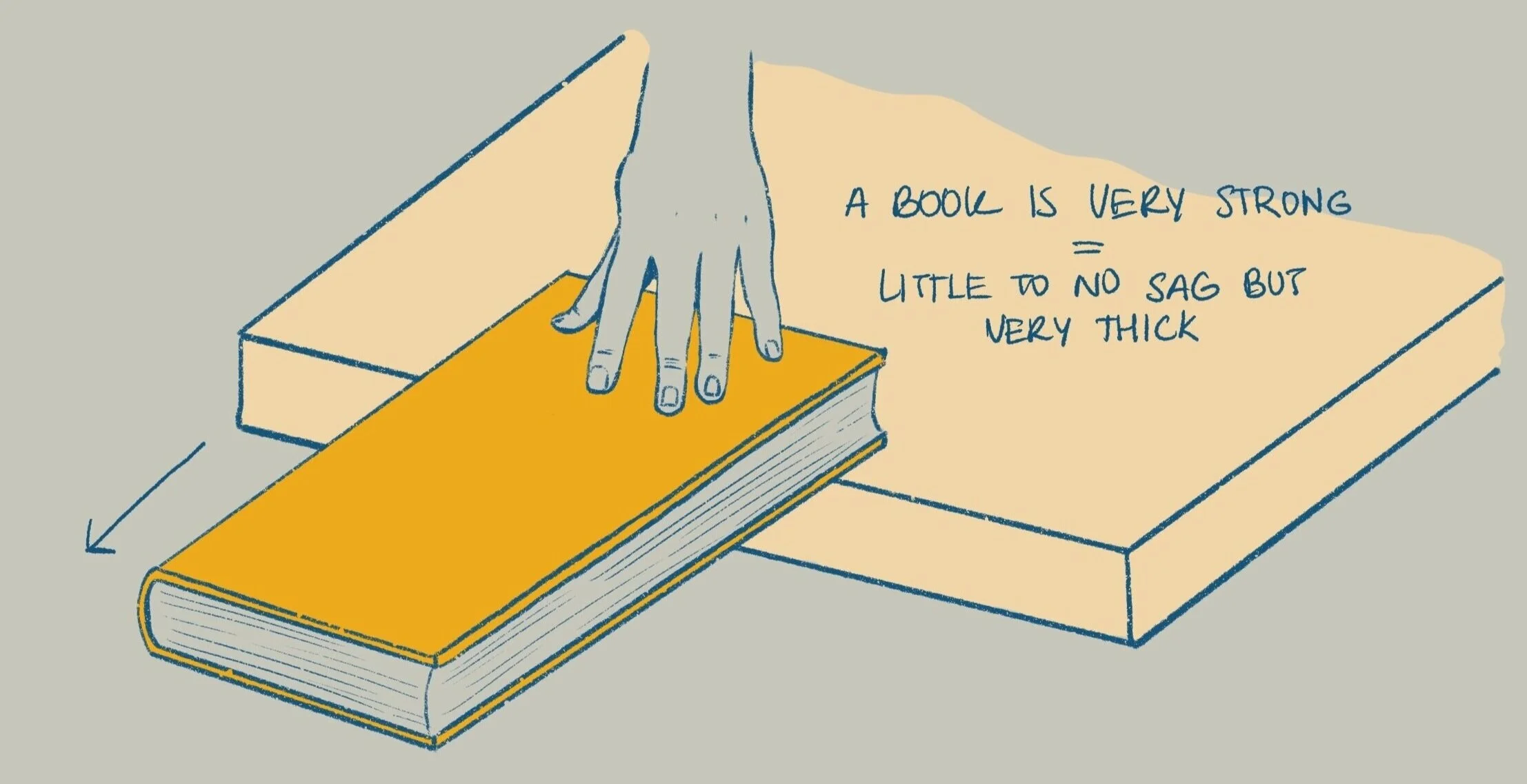
Grab a hardcover book and try this: While holding the book at the edge with one hand, push down at different points of the book with the other hand. Observe how this affects the pressure on your holding hand or even if the book bends. The further you are from your hand, the more the book will push up on your holding hand, because it creates a torque.
A torque is a turning effect the book would go through from you pushing at the end of the book. While you push down at one end of the book, your holding hand will feel a force pushing up. Similar forces would be on a real roof where you might have people walking around doing maintenance work, snow, or wind pushing in different directions.
With a book you have a strong and stiff overhang, but it’s also really thick. The architect would hate that! Stiffness and strength depend on the length and thickness of our material so, you can start to see why this thin roof was a challenge. Basically, the goal for the design of this roof was to have the strength of a book but as thin as cardboard.
Trusses and more metal bars
For engineers, using a book for a roof would be like using an enormous block of steel or concrete, that’s too heavy, expensive, and not practical at all. Instead, we try to use as little materials and get as much strength from each component. To understand how the roof came to be, we have to understand how a structural engineer would approach designing it. Engineers often start with trusses as building block for roofs, as trusses are light and strong.
You might have seen these used in bridges usually made of steel or wood, or even on the roof of your house. To give you an idea of how this looks, one of the most iconic truss structures is the Eiffel Tower. Below are two types of Warren trusses, the name is just based on who first designed it, but there are many types as you can experiment with the shape, number of bars, and layout.

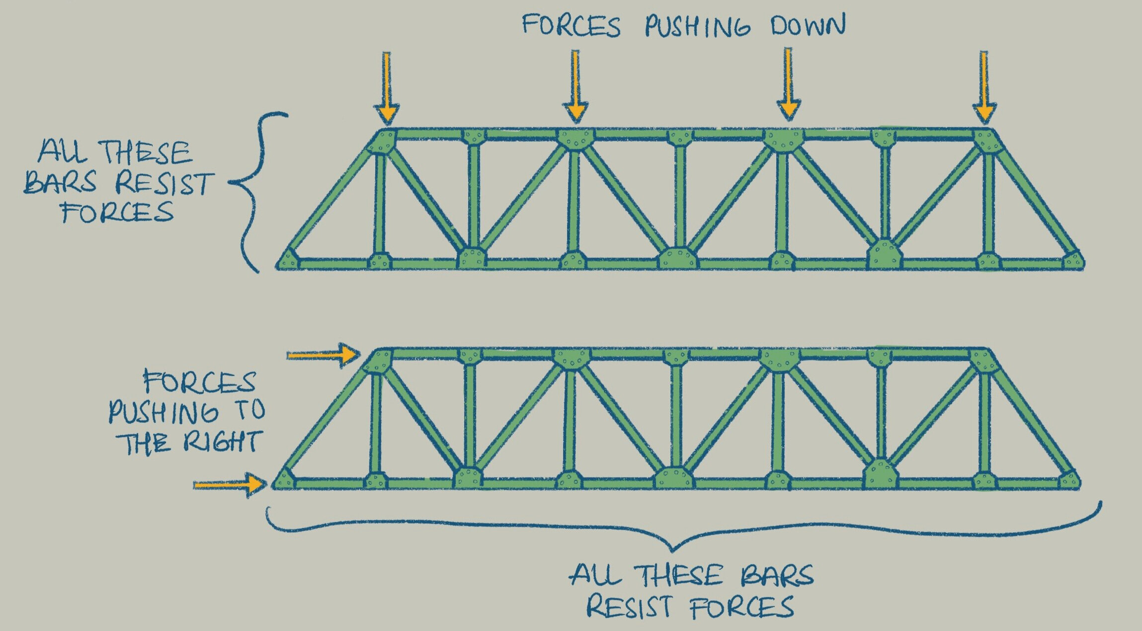
Trusses work by adding metal bars, called cords. These cords are either pulled or squished (tension or compression) so you only have bars where you need them. This makes trusses very efficient without much excess material. They are also great because you can use triangular shapes to your advantage, which are very strong geometric shapes!
BUT….
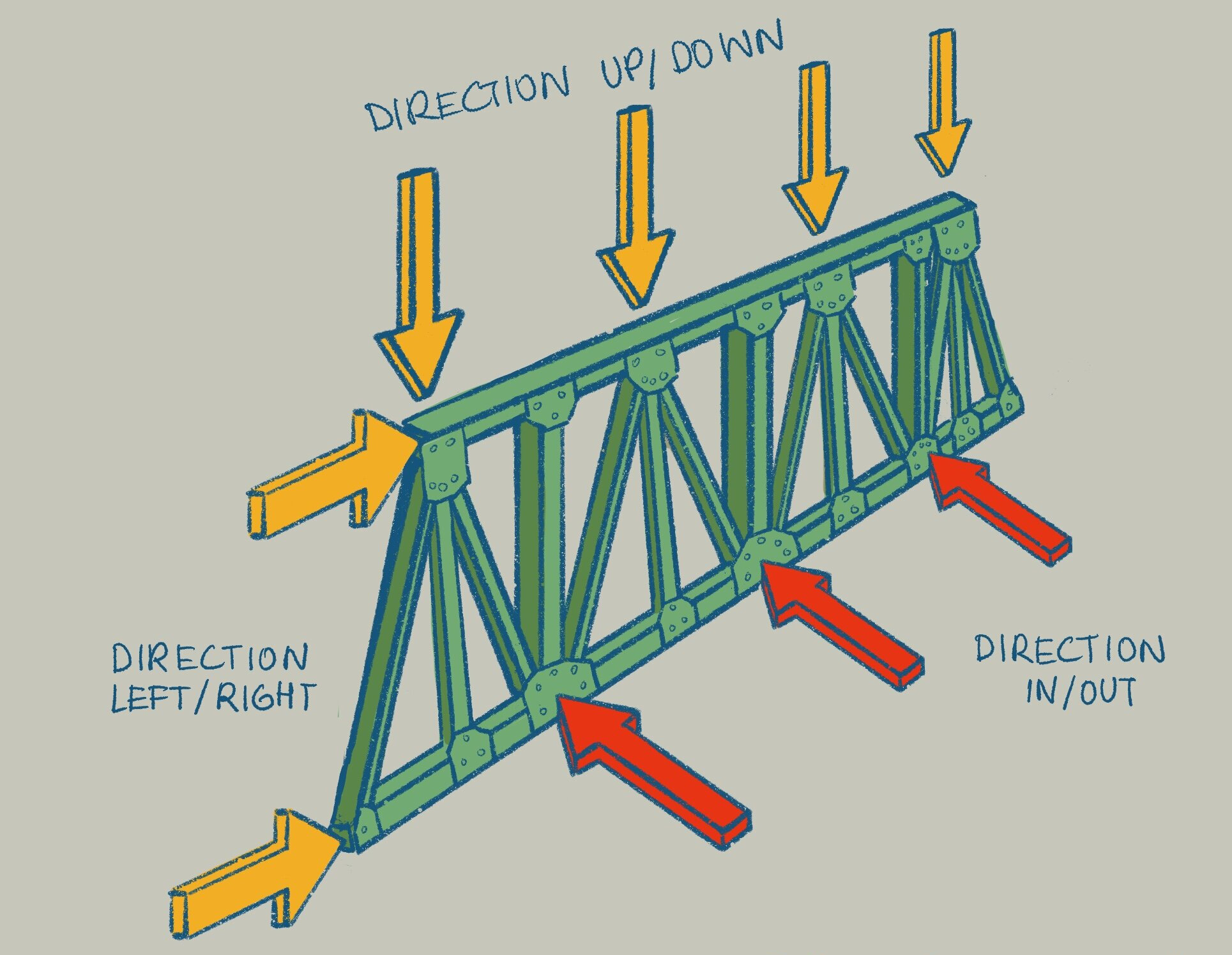
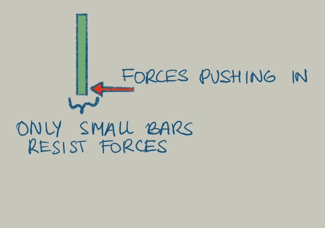
Trusses are strong in only two directions in this case up/down and right/left, but when you load them in a third direction, in/out they only have a tiny area to support that. So, grab a softcover book with the binding facing down and push up/down, left/right, and finally in/out. You’ll see that the book bends the most in the in/out direction. Below, the yellow arrows on the truss represent pushing down and to the right while the red arrows push out.
A way to counteract this weakness in the in/out direction is to use bracing bars. Braces are just metal bars that connect trusses together to disperse the load between as many trusses as possible/needed.


However, in this specific case bracing was not enough to support the entire roof with trusses. We need something stronger and stiffer.
One might suggest beams. Beams are solid or sometimes hollow blocks of steel, wood, concrete, etc. The most common type of steel beam is the I-beam as shown below

The I-beam shape was designed to have material where it needs it the most, top and bottom and a little in the middle. Beams work differently than trusses, they work in bending similar to a celery stick or a carrot. If you can grab a carrot from your fridge and try to hold it from both ends, creating a carrot bridge, and imagine you load it in the middle. In this case the carrot will also bend down in the middle. The top side will be in compression and the bottom side in tension. If you keep pushing, you’ll notice that the carrot will always break because of the tension, therefore, break at the bottom. Here, however, we need something even stronger and stiffer to resist all the forces and adapt to the round shape of the foyer.
The next best thing is a structural member that is almost exclusively used in bridges. A box girder comes from a very simple combination of beams, but it can create a really powerful section in all directions.

Picture you have a bunch of beams supporting a deck.

The heavier the load or longer the distance, the bigger the beams get.

Eventually they get so big that there is not enough space, so each beam touches each other. See those squares that have formed with the beams?

We can reorganize these square sections and create a new geometry; called a box girder.

As this is a custom-made component, each engineer can design their own and adjust it to the project’s needs. To the left you see the opera’s box girders. This box girder is hollow in the horizontal direction and the vertical direction to accommodate for windows. When used in bridges, box girders are only hollow in the horizontal direction.
This new structural member is just as strong as a group of I-beams, but the custom shape allows for better fit to the project and it is more resistant to twisting that wind might cause. The one big aspect for why these are not used all over the roof is that a box girder is custom made, so they are pricier to make and install.
Roof layout
So, now that you know what trusses, braces, beams, and box girders are, the last challenge is how to lay these all out and get the best performance out of each of them. A smart way to lay these sections would be to organize them from light to heavy. Below is a diagram of how the roof looks.


The key was to use the custom shape of the box girders over the foyer area that is circular and needs openings. It is also the area where we need the most strength since, just like the book experiment we did, this is the area where you would feel the most load.
Then use trusses to make the rest of the structure light and strong. Wherever the structure is not strong enough, place braces to connect each truss together and get the most strength out of each. As you can see, braces are not only used with trusses, you can also use them with beams and box girders to make things even stronger. Some braces are not shown in this diagram for clarity, but if you look at the summary poster at the end of the article, you’ll see many braces that go along the roof to strengthen the structure.
Finally, you might see some metal plates that we didn’t cover in the explanation. These are mostly used similar to tiny beams where they carry little loads and are just there to supplement other members.
The lie about this roof
Now, through this whole design, the big challenge was to make the roof as thin as possible. But do you really need the roof to be thin or does it just need to LOOK thin? Well, it turns out that the trusses and plates on the edges are smaller and thinner than the ones in the rest of the structure, so from anywhere you look the roof looks thinner than what it really is.
Below is a summary poster showing an overview of all the components discussed in this article and a detailed look of the structure.
I hope you were able to get a glimpse on the wonderful world of civil engineering. We talked about stiffness, strength, cantilevers, and how different components can form such a cool structure. Keep an eye out and observe the buildings around you, maybe you can spot some interesting beams, trusses or even box girders! I hope you enjoyed reading this article and you join me in exploring more of these structures in the future.
If you liked this article please consider filling out this 5 question survey! https://forms.gle/i5AuNNw6gEm7AynR7
Bibliography:
Copenhagen Opera House plans and calculations
The Royal Danish Opera - Architects Website https://henninglarsen.com/en/projects/0400-0599/0553-operaen
LUSAS FEM Case Study https://www.lusas.com/case/civil/copenhagen_opera_house.html
The Complexity of the Copenhagen Opera House roof |Finite Element Analysis using LUSAS https://www.structuresinsider.com/post/the-complexity-of-the-copenhagen-opera-house-roof-finite-element-analysis-using-lusas
The Royal Danish Opera / Henning Larsen https://www.archdaily.com/915153/the-royal-danish-opera-henning-larsen?ad_medium=widget&ad_name=navigation-prev
Wikipedia article https://en.wikipedia.org/wiki/Copenhagen_Opera_House?oldformat=true